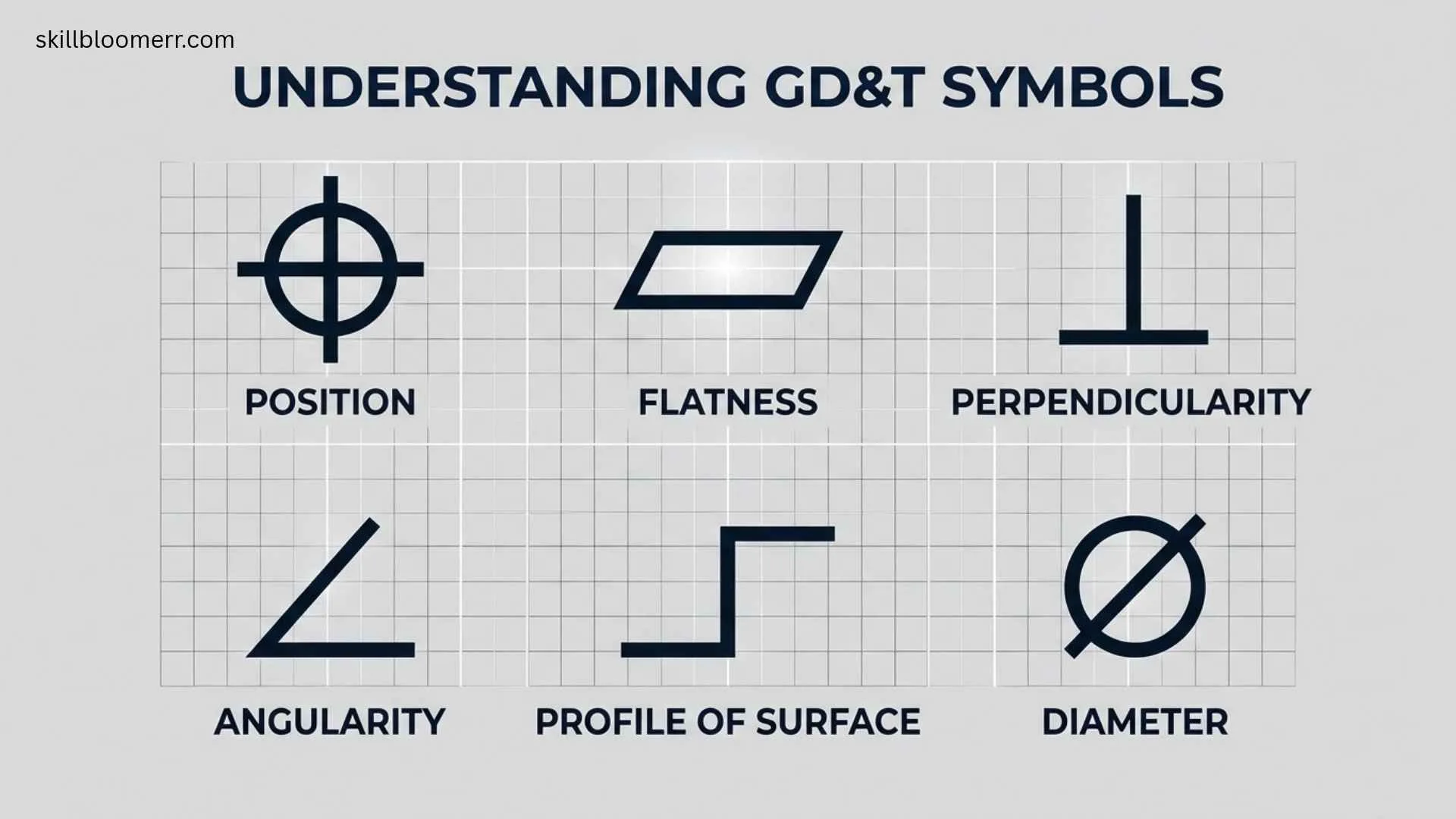
GD & T symbols are a standardized language used in engineering drawings to communicate precise manufacturing requirements. These symbols help designers, engineers, machinists, and inspectors understand how a part should be built, measured, and assembled.
Unlike simple dimensions that only describe size, GD & T symbols define the acceptable limits of variation for a part’s geometry, location, orientation, and form.
They are widely used in industries such as aerospace, automotive, medical devices, electronics, and precision manufacturing.
Understanding GD & T symbols is essential because even a small misunderstanding in a drawing can lead to incorrect parts, assembly problems, increased costs, and manufacturing delays. This guide explains the meaning, history, applications, variations, and practical importance of GD & T symbols.
Quick Meaning of GD & T Symbols
GD & T symbols are graphical markings used on engineering drawings to define the allowable variation of a part’s features. GD & T stands for Geometric Dimensioning and Tolerancing. These symbols specify requirements such as flatness, position, parallelism, perpendicularity, and runout, ensuring accurate manufacturing and inspection.
GD & T Symbols Overview Table
| Symbol Name | Primary Meaning | Category | Origin | First Known Use | Common Usage |
| Flatness | Controls surface accuracy | Form Control | Engineering Standards | 20th century | Machined surfaces |
| Straightness | Controls line or axis variation | Form Control | Engineering Standards | 20th century | Shafts, edges |
| Circularity | Controls roundness | Form Control | Engineering Standards | 20th century | Holes, cylinders |
| Cylindricity | Controls entire cylindrical surface | Form Control | Engineering Standards | 20th century | Precision shafts |
| Parallelism | Controls parallel relationship | Orientation Control | Engineering Standards | 20th century | Mechanical assemblies |
| Perpendicularity | Controls 90-degree relationship | Orientation Control | Engineering Standards | 20th century | Blocks, brackets |
| Angularity | Controls angled surfaces | Orientation Control | Engineering Standards | 20th century | Sloped features |
| Position | Controls feature location | Location Control | Engineering Standards | 20th century | Holes and slots |
| Concentricity | Controls shared center alignment | Location Control | Engineering Standards | 20th century | Rotating components |
| Symmetry | Controls balanced geometry | Location Control | Engineering Standards | 20th century | Symmetrical parts |
| Circular Runout | Controls rotation variation | Runout Control | Engineering Standards | 20th century | Bearings, shafts |
| Total Runout | Controls complete surface variation | Runout Control | Engineering Standards | 20th century | Rotating surfaces |
What Do GD & T Symbols Mean?
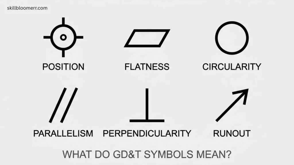
GD & T symbols represent specific geometric requirements that define how much a manufactured feature can vary from its ideal design.
A normal engineering drawing might show a hole diameter as:
10 mm
This only explains the size of the hole.
A GD & T drawing may include:
10 mm diameter with position tolerance
This tells manufacturers where the hole must be located and how much deviation is acceptable.
GD & T separates different types of requirements:
- Size requirements
- Shape requirements
- Location requirements
- Orientation requirements
- Surface movement requirements
This makes engineering drawings clearer and reduces confusion between designers and manufacturers.
Why GD & T Symbols Matter in Engineering
GD & T symbols exist because manufacturing processes naturally create small variations. No machine can produce a perfectly identical part every time.
These symbols provide a controlled method for answering important questions:
- How flat should this surface be?
- How accurately should two holes align?
- How much can a shaft move while rotating?
- How perpendicular should two surfaces remain?
Without GD & T, manufacturers would rely on assumptions, which could cause:
- Poor fitting parts
- Assembly failures
- Increased production waste
- Higher inspection costs
GD & T creates a common technical language between engineers, manufacturers, and quality inspectors.
History and Origin of GD & T Symbols
Development of Engineering Tolerances
The need for dimensional control increased during the Industrial Revolution when manufacturers began producing large numbers of interchangeable parts.
Early engineering drawings mainly showed measurements and basic dimensions. However, manufacturers soon discovered that two parts with identical dimensions could still fail to work together because their shapes and positions were slightly different.
This led engineers to develop more advanced tolerance systems.
Evolution Into Modern GD & T
Modern GD & T developed throughout the 20th century as industries required higher precision.
Organizations such as:
- American Society of Mechanical Engineers (ASME)
- International Organization for Standardization (ISO)
helped establish standards for geometric tolerancing.
Today, GD & T is commonly based on standards such as:
- ASME Y14.5
- ISO GPS (Geometrical Product Specifications)
These standards allow engineers worldwide to interpret drawings consistently.
Understanding the Main Categories of GD & T Symbols
GD & T symbols are divided into several groups based on what they control.
Form Control Symbols
Form controls define the shape of individual features without referencing another feature.
Flatness Symbol
The flatness symbol controls how much a surface can deviate from a perfectly flat plane.
Example uses:
- Machine bases
- Sealing surfaces
- Precision plates
A flatness requirement ensures that a surface does not contain excessive bends or uneven areas.
Straightness Symbol
Straightness controls whether a line element or axis remains straight.
It is commonly used for:
- Shafts
- Edges
- Long mechanical parts
Circularity Symbol
Circularity controls how close a circular feature must be to a perfect circle.
Applications include:
- Bearings
- Pipes
- Holes
Cylindricity Symbol
Cylindricity controls the entire shape of a cylindrical feature.
It considers:
- Roundness
- Straightness
- Taper
It is important for precision rotating parts.
Orientation Control Symbols
Orientation controls describe how one feature relates to another.
Parallelism Symbol
Parallelism ensures that two surfaces or features remain evenly aligned.
Common examples:
- Sliding components
- Guide rails
- Machine surfaces
Perpendicularity Symbol
Perpendicularity controls whether a feature maintains a 90-degree relationship.
Examples:
- Mounting brackets
- Engine components
- Structural parts
Angularity Symbol
Angularity controls a feature at a specific angle other than 90 degrees.
It is used for:
- Tapered surfaces
- Inclined components
- Precision assemblies
Location Control Symbols
Location controls define where features must be placed.
Position Symbol
The position symbol is one of the most commonly used GD & T symbols.
It controls:
- Hole locations
- Slots
- Pattern alignment
For example, a bolt hole pattern in a vehicle part may require exact positioning so another component fits correctly.
Concentricity Symbol
Concentricity controls whether two cylindrical features share the same center axis.
It is important for:
- Rotating shafts
- Mechanical assemblies
Symmetry Symbol
Symmetry ensures that features are evenly positioned around a center plane.
Runout Control Symbols
Runout controls measure how much a feature changes during rotation.
Circular Runout
Circular runout controls variation at individual circular sections.
Used for:
- Rotating shafts
- Wheels
- Discs
Total Runout
Total runout controls the entire surface while rotating.
It provides stricter control for high-precision components.
Symbolism and Interpretation of GD & T
GD & T symbols do not have cultural symbolism like ancient symbols or religious signs. Their meaning is technical and based on international engineering communication.
However, they represent important concepts:
Precision
GD & T symbolizes the pursuit of accuracy in design and manufacturing.
Reliability
Correct geometric control helps create safer and more dependable products.
Standardization
These symbols allow engineers from different countries to understand the same technical requirements.
Quality Control
GD & T represents a systematic approach to reducing errors.
Cultural and Industrial Significance
GD & T symbols are used globally in manufacturing cultures.
United States
The United States commonly uses ASME Y14.5 standards. Industries such as aerospace, automotive, and defense rely heavily on GD & T.
Europe
Many European manufacturers use ISO GPS standards for geometric specifications.
Asia
Countries with major manufacturing industries, including Japan, China, and South Korea, use GD & T principles extensively.
Although standards may differ slightly, the goal remains the same: creating accurate and reliable products.
Scientific and Technical Meaning of GD & T Symbols
GD & T is closely connected with mathematics, physics, and engineering science.
It involves:
- Coordinate systems
- Measurement science
- Manufacturing processes
- Statistical variation
- Quality engineering
Modern inspection methods use advanced equipment such as:
- Coordinate Measuring Machines (CMM)
- Laser scanners
- Optical measurement systems
These technologies compare manufactured parts against GD & T requirements.
Where GD & T Symbols Are Used
Engineering Drawings
The primary use of GD & T symbols is technical drawings.
Automotive Industry
Used for:
- Engine parts
- Transmission components
- Suspension systems
Aerospace Industry
Aircraft components require extremely precise tolerances because safety depends on accuracy.
Medical Devices
Used in:
- Surgical tools
- Implants
- Diagnostic equipment
Manufacturing and Machining
Machinists use GD & T symbols to understand production requirements.
Quality Inspection
Inspectors use GD & T to determine whether parts meet design specifications.
Common GD & T Symbol Variations
GD & T symbols may appear differently depending on the standard used.
Common variations include:
- ASME-based symbols
- ISO-based symbols
- Digital CAD representations
Modern CAD software such as engineering design programs allows engineers to insert GD & T symbols directly into 3D models.
Common Misconceptions About GD & T Symbols
GD & T Is Only About Dimensions
This is incorrect. GD & T controls geometry, relationships, and allowable variation.
More Tolerance Always Means Better Quality
Not always. Extremely tight tolerances can increase manufacturing costs without improving performance.
GD & T Is Only for Large Companies
Small manufacturers also use GD & T to improve accuracy and reduce mistakes.
All GD & T Standards Are Identical
Different organizations may use slightly different rules, so engineers must follow the required standard.
Interesting Facts About GD & T Symbols
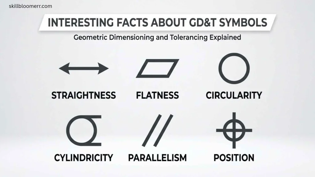
- GD & T Is a Universal Engineering Language
Engineers around the world use similar symbols to communicate manufacturing requirements. - GD & T Reduces Manufacturing Arguments
Clear symbols prevent disagreements between designers and manufacturers. - Position Is One of the Most Used Controls
Many modern drawings rely heavily on position tolerances. - GD & T Supports Interchangeable Parts
It helps manufacturers produce parts that fit together correctly. - GD & T Works With Modern CAD Systems
Digital models can include complete geometric requirements. - GD & T Is Important in Aerospace Safety
Aircraft components require strict geometric control. - GD & T Saves Money When Applied Correctly
Proper tolerances prevent unnecessary precision and reduce waste. - GD & T Combines Mathematics and Manufacturing
It connects design theory with real production processes. - Inspection Equipment Uses GD & T Data
CMM machines often measure parts according to GD & T requirements. - GD & T Continues to Evolve
New manufacturing technologies require updated approaches to geometric control.
Related Engineering Symbols
Welding Symbols
Welding symbols describe joining requirements between materials.
Surface Finish Symbols
These symbols specify surface texture and roughness.
Machining Symbols
Machining symbols communicate manufacturing processes.
Electrical Symbols
Electrical symbols represent circuits and components rather than mechanical geometry.
Blueprint Symbols
Blueprint symbols provide information about construction and engineering designs.
Frequently Asked Questions About GD & T Symbols
What does GD & T stand for?
GD & T stands for Geometric Dimensioning and Tolerancing. It is a system used on engineering drawings to define acceptable variations in part geometry, size, location, and orientation.
Why are GD & T symbols used?
GD & T symbols are used to improve communication between designers, manufacturers, and inspectors. They clearly explain how accurate a part must be and reduce manufacturing errors.
How many GD & T symbols are there?
GD & T contains several symbols grouped into form, orientation, location, and runout controls. The exact list depends on the standard being followed, such as ASME Y14.5.
What is the most common GD & T symbol?
The position symbol is among the most frequently used because it controls the location of holes and other important features in manufactured parts.
Are GD & T symbols used worldwide?
Yes. GD & T principles are used internationally in industries including aerospace, automotive, electronics, and medical manufacturing.
What is the difference between dimensions and GD & T?
Dimensions describe size measurements, while GD & T describes acceptable geometric variation and relationships between features.
Do CAD programs use GD & T symbols?
Yes. Modern CAD software allows engineers to add GD & T information directly into drawings and digital models.
Who uses GD & T symbols?
Mechanical engineers, designers, machinists, manufacturers, quality inspectors, and technicians commonly use GD & T symbols.
Is GD & T difficult to learn?
GD & T requires practice because it combines drawing interpretation, mathematics, and manufacturing concepts. Learning the basic symbol groups makes it easier to understand.
What standard defines GD & T symbols?
The ASME Y14.5 standard is one of the most widely recognized standards for GD & T practices.
Key Takeaways
- GD & T symbols create a universal language for engineering drawings.
- They define acceptable variation in part geometry and location.
- GD & T improves manufacturing accuracy and product quality.
- Common categories include form, orientation, location, and runout controls.
- Position, flatness, perpendicularity, and runout are widely used symbols.
- GD & T is important in aerospace, automotive, medical, and manufacturing industries.
- Different countries may follow ASME or ISO standards.
- Correct use of GD & T reduces errors and production costs.
Conclusion
GD & T symbols are essential tools that transform engineering ideas into accurate physical products. They provide a precise method for describing how parts should be shaped, positioned, and manufactured.
From aerospace components to everyday automotive parts, these symbols help ensure reliability, safety, and consistency. Understanding GD & T symbols allows engineers, manufacturers, and inspectors to communicate clearly and produce high-quality results.
As manufacturing technology continues to advance, GD & T will remain a fundamental part of modern engineering design and precision production.

I’m Olivia Hartwell, a writer passionate about learning, personal growth, and practical education. I enjoy researching new ideas and sharing them in a way that feels easy to understand and useful. Through my work with SkillBloomerr, I aim to give readers reliable information they can apply in real life.
Books: Small Steps, Big Growth and The Curious Mind
 Nathaniel Brooks