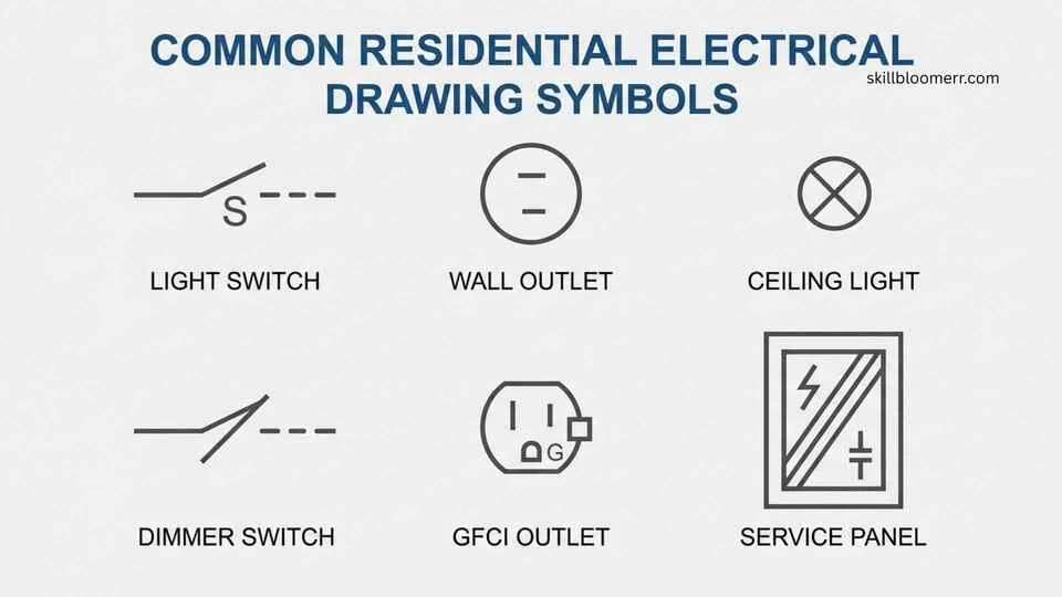
Electrical drawing symbols for house plans are the universal language used by electricians, architects, engineers, builders, and homeowners to communicate how a home’s electrical system should be installed. Instead of lengthy written instructions, standardized symbols represent outlets, switches, lights, circuit breakers, fans, smoke detectors, electrical panels, and dozens of other components.
Whether you’re building a new home, remodeling a kitchen, planning a room addition, or simply trying to understand your home’s electrical blueprint, learning these symbols can save time, reduce misunderstandings, and improve safety. A properly labeled electrical drawing allows everyone involved in a construction project to interpret the same information regardless of language or location.
Residential electrical symbols are based on recognized drafting standards developed by professional organizations and have evolved alongside modern electrical technology. While some symbols vary slightly between countries or design firms, most follow similar principles, making electrical plans easier to read worldwide.
This guide explains what electrical drawing symbols for house plans mean, where they came from, how they are used, and how to interpret them correctly.
Quick Meaning of Electrical Drawing Symbols for House:
Electrical drawing symbols for house plans are standardized graphical representations used on residential electrical blueprints to identify electrical devices, wiring, fixtures, outlets, switches, safety equipment, and circuits. They simplify communication between designers, electricians, inspectors, and homeowners, ensuring accurate installation and compliance with electrical codes.
Symbol Overview Table
| Feature | Details |
| Symbol Name | Electrical Drawing Symbols for House |
| Primary Meaning | Graphical representations of electrical devices and circuits |
| Category | Technical Drawing Symbols |
| Industry | Electrical Engineering, Architecture, Construction |
| Origin | Engineering drafting standards |
| First Known Use | Early 20th-century electrical drafting practices |
| Common Usage | Residential electrical plans and blueprints |
| Modern Meaning | Standardized visual language for residential electrical systems |
| Primary Users | Electricians, Architects, Engineers, Contractors, Inspectors |
| Standards | IEEE, IEC, ANSI, NEC-related drafting practices, ISO drafting conventions |
| Purpose | Improve communication and reduce installation errors |
| Related Symbols | Switch symbols, outlet symbols, lighting symbols, wiring symbols, panel symbols |
What Does Electrical Drawing Symbols for House Mean?
Electrical drawing symbols for house plans represent the physical electrical components that will be installed in a residential building. Rather than drawing each device realistically, technical drawings use simple symbols that professionals immediately recognize.
These symbols make blueprints cleaner, easier to understand, and faster to produce. Imagine trying to draw every electrical outlet, ceiling fan, or light fixture in full detail on a floor plan—it would become cluttered and difficult to read. Symbols solve this problem by providing a consistent visual shorthand.
Why These Symbols Exist
Every residential electrical project involves multiple professionals. An architect designs the home, an electrical engineer may prepare the electrical layout, electricians install the system, inspectors verify code compliance, and homeowners review the finished plans.
Without standardized symbols, each person could interpret the plans differently, leading to costly mistakes or unsafe installations.
Standard symbols help ensure:
- Clear communication
- Accurate installations
- Faster blueprint reading
- Reduced construction errors
- Easier inspections
- Better maintenance and future renovations
What Information Do Electrical Symbols Convey?
Electrical symbols communicate much more than the existence of a device. They often indicate:
- Device type
- Mounting location
- Installation height
- Circuit assignment
- Control method
- Power requirements
- Special functions
- Safety equipment
- Emergency systems
For example, two outlet symbols may look similar, but one could indicate a standard duplex receptacle while another represents a Ground Fault Circuit Interrupter (GFCI) outlet required in bathrooms and kitchens.
Common Categories of Residential Electrical Symbols
Residential electrical drawings typically group symbols into several categories:
Lighting Symbols
Lighting symbols indicate all forms of illumination throughout the home, including:
- Ceiling-mounted lights
- Recessed lighting
- Pendant fixtures
- Chandeliers
- Wall sconces
- Exterior lights
- Floodlights
- Track lighting
- Under-cabinet lighting
Each symbol helps installers identify the exact fixture type and placement.
Switch Symbols
Switch symbols show how lights and devices are controlled.
Common examples include:
- Single-pole switch
- Double-pole switch
- Three-way switch
- Four-way switch
- Dimmer switch
- Timer switch
- Motion sensor switch
- Smart switch
Different markings indicate different switching functions.
Receptacle Symbols
Outlet symbols identify the electrical receptacles installed throughout a house.
These may include:
- Standard duplex outlet
- GFCI receptacle
- AFCI-protected outlet
- Weatherproof outlet
- Floor receptacle
- USB outlet
- Dedicated appliance outlet
- 240-volt outlet
The symbol tells electricians not only where to place the outlet but also its electrical characteristics.
Wiring Symbols
Wiring symbols illustrate electrical connections between devices.
They may indicate:
- Hidden wiring
- Surface wiring
- Home-run circuits
- Junction boxes
- Conduit routing
- Cable pathways
- Branch circuits
These symbols provide the roadmap electricians follow during installation.
Equipment Symbols
Modern homes contain many electrical devices beyond basic lights and outlets.
Equipment symbols often include:
- Smoke detectors
- Carbon monoxide detectors
- Doorbells
- Security systems
- Ceiling fans
- Exhaust fans
- HVAC controls
- Electric water heaters
- Electric ranges
- Air-conditioning disconnects
- Solar equipment
- Backup generators
Each symbol represents a specific electrical component with unique installation requirements.
Why Homeowners Should Learn These Symbols
Although electrical plans are primarily designed for professionals, homeowners also benefit from understanding them.
Knowing common electrical symbols helps homeowners:
- Review renovation plans confidently.
- Discuss projects with contractors.
- Request changes before construction begins.
- Understand electrical upgrades.
- Locate hidden wiring.
- Plan furniture placement around outlets.
- Prepare for future remodeling.
Even a basic understanding of electrical drawing symbols can prevent misunderstandings during home improvement projects.
History and Origin
Electrical drawing symbols originated from the need to standardize technical communication as electricity became a common feature in homes and commercial buildings during the late nineteenth and early twentieth centuries.
Early Electrical Drawings
Before standardized symbols existed, electrical installations were often documented using handwritten notes and detailed sketches. Because every engineer or contractor developed their own notation, drawings varied widely and were difficult for others to interpret.
As electrical systems became more complex, this inconsistency created confusion, increased construction errors, and made maintenance more difficult.
Standardization in the Twentieth Century
The rapid growth of electrification during the early 1900s led engineering organizations to develop standardized drafting symbols.
Professional bodies such as:
- Institute of Electrical and Electronics Engineers (IEEE)
- International Electrotechnical Commission (IEC)
- American National Standards Institute (ANSI)
- International Organization for Standardization (ISO)
contributed to creating consistent methods for representing electrical components on technical drawings.
Although building codes like the National Electrical Code (NEC) govern safe electrical installations in the United States, drafting symbols themselves are generally guided by industry standards and company drafting practices rather than a single mandatory symbol set.
Evolution of Residential Electrical Symbols
As homes became more technologically advanced, electrical symbols expanded beyond simple lights and switches.
New symbols were developed for:
- Ground fault protection
- Arc fault protection
- Smart home controls
- Solar photovoltaic systems
- Electric vehicle charging stations
- Home automation devices
- Structured cabling
- Fiber optic connections
- Network outlets
- USB charging receptacles
- Battery backup systems
This evolution reflects changing lifestyles and advances in residential technology.
From Paper Blueprints to Digital CAD
Historically, electrical plans were drafted by hand using pencils, templates, rulers, and symbol stencils. Draftsmen spent countless hours producing detailed drawings on large sheets of paper.
Today, most residential electrical plans are created using Computer-Aided Design (CAD) and Building Information Modeling (BIM) software. These digital tools include built-in libraries of standardized symbols, allowing designers to produce accurate, editable, and highly detailed electrical layouts more efficiently.
Despite the shift from paper to digital drafting, the underlying symbols remain largely recognizable, ensuring continuity across generations of construction professionals.
Why Standardization Matters Today
Modern residential projects often involve teams spread across different companies and specialties. A standardized symbol for a smoke detector or a three-way switch allows architects, electricians, inspectors, and suppliers to interpret the same drawing consistently.
This shared visual language reduces errors, speeds construction, supports code compliance, and simplifies future maintenance or renovations.
(Continued in Part 2: Symbolism and Interpretation, Scientific or Technical Meaning, Cultural Significance, and Where Electrical Drawing Symbols Are Used.)
Symbolism and Interpretation

Electrical drawing symbols for house plans are functional rather than symbolic in the cultural or artistic sense. Their primary purpose is to communicate technical information quickly and accurately. Even so, they represent important concepts such as safety, organization, connectivity, and efficient power distribution within a home.
Unlike religious or cultural symbols that may have multiple interpretations, electrical symbols are designed to have a single, standardized meaning. This minimizes confusion during construction and helps ensure that every electrical component is installed in the correct location.
Traditional Interpretation
From a drafting perspective, each symbol acts as a visual shorthand for a real-world electrical device. The meaning is fixed by industry practice rather than personal interpretation.
For example:
- A receptacle symbol indicates a power outlet.
- A switch symbol shows where electrical control is provided.
- A light fixture symbol identifies the location of illumination.
- A panel symbol marks the home’s electrical distribution center.
These symbols allow professionals to understand an entire electrical system at a glance without reading lengthy descriptions.
Modern Interpretation
Today’s residential electrical drawings include symbols for technologies that did not exist decades ago. As homes have become smarter and more energy-efficient, the meaning of many drawings has expanded beyond basic wiring.
Modern electrical plans may include symbols for:
- Smart switches
- Smart lighting controls
- Wi-Fi access points
- Data outlets
- Electric vehicle (EV) chargers
- Solar photovoltaic systems
- Battery energy storage
- Home automation hubs
- Security cameras
- Motion sensors
- Smart thermostats
These additions reflect how residential electrical systems now support communication, automation, renewable energy, and digital connectivity alongside traditional power distribution.
Positive Symbolism in Engineering
Although technical, electrical drawing symbols also represent several broader engineering values:
Safety
Every symbol contributes to creating a safe electrical installation. Proper placement of outlets, protective devices, smoke alarms, and emergency disconnects reduces electrical hazards and helps protect occupants.
Organization
A well-prepared electrical drawing demonstrates careful planning. Symbols show how every device fits into the home’s overall electrical design, making installation and future maintenance more efficient.
Precision
Technical symbols eliminate ambiguity. Instead of relying on written descriptions that could be misunderstood, symbols provide a universally recognized visual language.
Communication
Electrical drawings enable architects, engineers, electricians, contractors, inspectors, and homeowners to work from the same set of instructions. This shared understanding reduces costly mistakes during construction.
Potential Negative Consequences of Misinterpreting Symbols
The symbols themselves carry no negative meaning, but misunderstanding them can have serious consequences.
Possible issues include:
- Incorrect wiring
- Improper outlet placement
- Overloaded circuits
- Unsafe installations
- Failed building inspections
- Construction delays
- Increased project costs
- Fire hazards
- Electrical shock risks
For this reason, professionals rely on standardized legends and detailed electrical schedules to clarify any project-specific symbols used on a drawing.
Psychological Interpretation
From a human factors perspective, symbols reduce cognitive load. Instead of processing long blocks of text, the brain can recognize familiar shapes almost instantly.
This improves:
- Blueprint readability
- Decision-making speed
- Construction efficiency
- Communication between trades
- Accuracy during installation
In technical drafting, consistency is just as important as creativity. A familiar symbol allows experienced professionals to understand complex plans quickly and confidently.
Cultural Significance
Electrical drawing symbols have little cultural symbolism compared with religious, historical, or artistic symbols. However, they play a significant role in the global construction industry because they provide a shared technical language across countries and professions.
An International Engineering Language
Electricity powers homes around the world, and professionals from different backgrounds often collaborate on construction projects. Standardized electrical symbols help bridge language barriers.
For example:
- An architect in Canada can prepare plans reviewed by an engineer in Germany.
- Components may be manufactured in Japan or South Korea.
- Electrical equipment might be installed by contractors in the United States or Australia.
Although notation styles may differ slightly, the core symbols are widely understood.
Regional Differences
Different countries follow different electrical standards, which can influence the appearance of symbols.
Examples include:
- North America commonly follows ANSI, IEEE, and NEC-related drafting conventions.
- Many European countries use IEC standards.
- Australia and New Zealand have their own drafting practices aligned with international standards.
- Japan may use symbols adapted to local electrical regulations.
- The United Kingdom follows British Standards (BS) for electrical documentation.
Because of these differences, professionals always review the drawing legend before beginning work.
Educational Importance
Electrical symbols are taught in:
- Trade schools
- Technical colleges
- Engineering programs
- Architecture schools
- Apprenticeship programs
- Vocational training centers
Learning these symbols is one of the first steps toward understanding residential electrical design.
Industry Recognition
Electrical drawings are recognized globally as essential construction documents. Building permits, inspections, renovations, and maintenance projects all rely on accurate electrical plans that use standardized symbols.
Scientific or Technical Meaning

From a technical standpoint, electrical drawing symbols represent real electrical components that work together to distribute, control, and protect electricity within a home. While the symbols themselves are graphical, each corresponds to equipment governed by electrical engineering principles and installation standards.
Lighting Symbols
Lighting symbols identify the type and placement of illumination throughout the house.
Common examples include:
- Ceiling-mounted light fixture
- Recessed downlight
- Pendant light
- Wall sconce
- Fluorescent fixture
- LED fixture
- Exterior floodlight
- Landscape lighting
Electrical plans often include switching arrangements that indicate which switch controls each light.
Switch Symbols
Switch symbols show how electrical circuits are opened or closed to control power.
Common residential switch symbols include:
| Switch Type | Purpose |
| Single-pole switch | Controls one light from one location |
| Three-way switch | Controls one light from two locations |
| Four-way switch | Controls one light from three or more locations |
| Double-pole switch | Controls 240-volt equipment |
| Dimmer switch | Adjusts lighting brightness |
| Timer switch | Operates equipment on a schedule |
| Motion sensor switch | Activates lighting when movement is detected |
Understanding these symbols helps electricians install proper switching arrangements.
Receptacle (Outlet) Symbols
Receptacle symbols indicate where electrical power is available throughout the home.
Common outlet symbols represent:
- Duplex receptacle
- Ground Fault Circuit Interrupter (GFCI)
- Arc Fault Circuit Interrupter (AFCI)-protected outlet
- Weather-resistant outlet
- Floor receptacle
- Dedicated appliance outlet
- 240-volt receptacle
- USB charging outlet
Special symbols distinguish outlets intended for kitchen appliances, laundry equipment, HVAC systems, and electric vehicle chargers.
Electrical Panel Symbols
The electrical panel serves as the distribution center for the home’s electrical system.
Panel symbols may indicate:
- Main service panel
- Subpanel
- Meter location
- Circuit breaker panel
- Disconnect switch
- Transfer switch for backup generators
These symbols are essential for identifying where electrical power enters and is distributed throughout the residence.
Wiring Symbols
Wiring symbols illustrate electrical connections between devices.
They may identify:
- Branch circuits
- Home-run wiring
- Junction boxes
- Conduit pathways
- Underground cable
- Flexible conduit
- Cable trays (where applicable)
Lines on the drawing often represent cable routes rather than the exact physical path of the wiring inside walls.
Grounding Symbols
Grounding protects both people and equipment from electrical faults.
Ground symbols may indicate:
- Equipment grounding conductor
- Earth ground
- Bonding connection
- Ground rod
- Ground bus
Proper grounding is one of the most important safety features shown on an electrical plan.
Safety Device Symbols
Modern homes include numerous safety devices represented by dedicated symbols.
These may include:
- Smoke detectors
- Carbon monoxide detectors
- Heat detectors
- Emergency lighting
- Exit lighting (where applicable)
- Surge protection devices
- Ground-fault protection
- Arc-fault protection
These components help reduce the risk of fire, electrical shock, and other hazards.
Communication and Low-Voltage Symbols
Today’s homes include more than standard power wiring.
Electrical plans often contain symbols for:
- Telephone outlets
- Ethernet ports
- Television outlets
- Fiber optic connections
- Doorbell systems
- Security sensors
- CCTV cameras
- Wireless access points
- Intercom systems
- Smart home controllers
Although these systems operate at lower voltages than standard electrical circuits, they are commonly shown alongside power systems for coordination during construction.
Where the Symbols Are Used
Electrical drawing symbols for house plans appear anywhere residential electrical systems need to be designed, installed, inspected, maintained, or modified. Their consistent use ensures that everyone involved in a project understands the intended electrical layout.
Residential Construction
The most common use is in the construction of new homes.
Before wiring begins, electricians rely on electrical plans to determine:
- Outlet locations
- Lighting placement
- Switch positions
- Circuit layouts
- Electrical panel configuration
- Smoke detector placement
- Dedicated appliance circuits
These drawings help ensure the installation matches the approved design.
Home Renovations and Remodeling
During remodeling projects, updated electrical drawings show changes to existing systems.
Examples include:
- Kitchen remodels
- Bathroom renovations
- Basement finishing
- Garage conversions
- Home additions
- Attic conversions
- Outdoor living spaces
Accurate symbols help contractors integrate new electrical work safely with the existing system.
Building Permit Applications
Many municipalities require electrical drawings as part of the permit approval process. Inspectors review these plans to verify compliance with applicable electrical codes before construction begins.
Electrical Inspections
Inspectors compare the completed installation with the approved electrical drawings. Symbols make it easy to confirm that outlets, switches, fixtures, and safety devices have been installed in the correct locations.
Maintenance and Troubleshooting
Years after a home is built, electricians use original electrical drawings to locate concealed wiring, identify circuit routes, and diagnose problems more efficiently.
Interior Design and Furniture Planning
Interior designers and homeowners also refer to electrical plans when arranging furniture, planning built-in cabinetry, or selecting lighting layouts. Knowing the location of outlets, switches, and ceiling fixtures helps avoid conflicts during installation and improves the functionality of each room.
Common Variations
Electrical drawing symbols for house plans are standardized, but they are not completely identical worldwide. Their appearance can vary depending on the drafting standard, country, software, project requirements, and the preferences of the engineering or architectural firm. Despite these visual differences, the underlying purpose of each symbol remains the same.
Understanding these variations helps readers interpret plans correctly and reduces the risk of mistakes during installation or renovation.
Variations by Drafting Standards
Different standards organizations publish recommended drafting practices.
Some of the most commonly referenced include:
- ANSI (American National Standards Institute) – Widely used in the United States.
- IEEE (Institute of Electrical and Electronics Engineers) – Provides engineering standards and technical guidance.
- IEC (International Electrotechnical Commission) – Commonly referenced in Europe and many other regions.
- ISO (International Organization for Standardization) – Supports international technical drawing conventions.
- BS (British Standards) – Used in the United Kingdom.
A duplex receptacle, for example, may appear as a simple circle with markings in one standard but use a slightly different graphical representation in another.
Variations in Lighting Symbols
Lighting fixtures have expanded significantly over the years, resulting in many specialized symbols.
Examples include:
| Lighting Type | Typical Representation |
| Ceiling light | Simple circle with designation |
| Recessed light | Small circle often labeled “R” |
| LED fixture | Fixture symbol with LED notation |
| Pendant light | Circle connected to ceiling by line |
| Chandelier | Decorative lighting symbol |
| Wall sconce | Half-circle attached to wall |
| Exterior floodlight | Directional lighting symbol |
| Under-cabinet light | Linear lighting notation |
Many electrical plans also assign identification numbers that correspond to a lighting schedule.
Switch Symbol Variations
Switches are often identified using letters and numbers.
Examples include:
- S = Single-pole switch
- S3 = Three-way switch
- S4 = Four-way switch
- SD = Dimmer switch
- ST = Timer switch
- SS = Smart switch
- MS = Motion sensor
Some companies use custom abbreviations, which is why every professional drawing includes a legend explaining project-specific notation.
Outlet Symbol Variations
Residential outlet symbols have expanded to represent modern electrical needs.
Examples include:
- Standard duplex outlet
- GFCI outlet
- AFCI-protected receptacle
- Weather-resistant outlet
- Floor outlet
- USB charging outlet
- Dedicated refrigerator outlet
- Microwave outlet
- Range outlet
- Dryer outlet
- EV charging receptacle
The symbol often includes labels indicating voltage, amperage, or special protection requirements.
Smart Home Symbols
Modern electrical drawings increasingly include symbols for connected devices.
Examples include:
- Smart thermostat
- Wi-Fi access point
- Smart lighting controller
- Voice assistant hub
- Automated blinds
- Security camera
- Video doorbell
- Smart lock
- Occupancy sensor
These symbols were rarely found on residential drawings just two decades ago but are becoming standard in new home construction.
Renewable Energy Symbols
As sustainable energy systems become more common, electrical plans may include symbols for:
- Solar panels
- Solar inverter
- Battery storage system
- EV charging station
- Energy monitoring equipment
- Automatic transfer switch
- Backup generator
- Grid connection point
These symbols help electricians integrate renewable energy systems with the home’s electrical infrastructure.
CAD and BIM Library Variations
Modern drafting software contains extensive symbol libraries. Different software packages may display the same device using slightly different graphics while preserving its meaning.
Popular software platforms include:
- AutoCAD
- AutoCAD Electrical
- Revit
- ArchiCAD
- SolidWorks Electrical
- Bentley MicroStation
Regardless of the software used, professional drawings include legends to explain project-specific symbols.
Common Misconceptions
Although electrical drawing symbols are designed to simplify communication, they are often misunderstood by homeowners and beginners. Clearing up these misconceptions makes electrical plans much easier to read.
Misconception 1: Every Country Uses Exactly the Same Symbols
This is not true.
Many symbols are similar because international standards influence drafting practices, but there are regional differences. Always review the legend provided with the drawing.
Misconception 2: Every Circle Represents a Light Fixture
Many people assume every circular symbol is a ceiling light.
In reality, circles may represent:
- Recessed lights
- Smoke detectors
- Ceiling fans
- Junction boxes
- Data outlets
- Specialty fixtures
Labels and legends provide the correct identification.
Misconception 3: Symbols Show the Exact Physical Shape
Electrical symbols are not pictures of real devices.
Instead, they are simplified diagrams designed for clarity.
For example, a wall switch symbol does not resemble an actual wall switch. It simply represents its function.
Misconception 4: Wiring Lines Show Exact Cable Routes
Blueprint wiring lines are generally schematic rather than literal.
Electricians often adjust cable routing during installation to comply with building structure, code requirements, and construction conditions.
Misconception 5: One Symbol Means Only One Product
A single lighting symbol may represent many compatible fixtures.
The actual fixture model is usually identified in:
- Lighting schedules
- Fixture schedules
- Specifications
- Construction notes
The symbol alone does not specify the brand or appearance.
Misconception 6: Homeowners Do Not Need to Understand Electrical Symbols
While homeowners are not expected to perform electrical work, understanding common symbols helps them:
- Review renovation plans.
- Communicate with contractors.
- Plan furniture layouts.
- Identify future expansion opportunities.
- Understand inspection reports.
Even basic symbol knowledge can make home improvement projects smoother.
Misconception 7: Electrical Symbols Never Change
Electrical drafting continues to evolve.
New technologies—including smart homes, renewable energy systems, and electric vehicles—require new symbols and updated drafting conventions.
Interesting Facts
Electrical drawing symbols may seem simple, but they have a fascinating history and practical importance. Here are ten facts that many people don’t know.
1. Electrical Symbols Save Thousands of Words
A complete residential electrical plan may contain hundreds of electrical devices. Standardized symbols replace lengthy written descriptions, making blueprints easier to create and interpret.
2. They Help Prevent Construction Errors
One incorrectly interpreted symbol can lead to misplaced outlets, incorrect wiring, or failed inspections. Standardization greatly reduces these risks.
3. They Are Used in Nearly Every New Home
Virtually every professionally designed residential construction project includes electrical drawings that rely on standardized symbols.
4. Digital Software Still Uses Traditional Symbols
Even advanced CAD and BIM software continues to use symbol libraries based on long-established drafting conventions, demonstrating the lasting value of standardized graphical communication.
5. Symbols Continue to Evolve
As new technologies emerge, additional symbols are introduced for devices such as EV chargers, battery storage systems, smart home controllers, and renewable energy equipment.
6. Electrical Drawings Support Future Renovations
Years after construction, original electrical plans help electricians locate hidden wiring and identify circuit layouts without opening unnecessary walls.
7. Legends Are Essential
No matter how experienced an electrician is, professionals always review the drawing legend because firms may introduce project-specific abbreviations or custom symbols.
8. Residential Plans Include More Than Power
Modern electrical drawings often combine power, lighting, communications, networking, security, and automation systems into one coordinated plan.
9. Safety Devices Have Their Own Symbols
Smoke detectors, carbon monoxide alarms, surge protectors, AFCI devices, and GFCI outlets each have dedicated symbols because they perform distinct safety functions.
10. Learning Symbols Improves Communication
Homeowners who understand basic electrical symbols can communicate more effectively with electricians, architects, inspectors, and contractors, reducing misunderstandings during construction or remodeling.
Related Symbols
Electrical drawing symbols for house plans belong to a much larger family of engineering and architectural symbols. Understanding related symbols helps readers interpret complete construction drawings with greater confidence.
| Related Symbol | Purpose | How It Differs |
| Lighting Symbol | Identifies lighting fixtures | Focuses specifically on illumination devices |
| Switch Symbol | Represents electrical controls | Indicates how circuits are turned on or off |
| Duplex Receptacle Symbol | Marks standard power outlets | Used only for electrical receptacles |
| GFCI Outlet Symbol | Indicates protected outlets | Specifically designed for shock protection in wet locations |
| Electrical Panel Symbol | Represents the service or distribution panel | Shows the central point for electrical distribution |
| Junction Box Symbol | Indicates wiring connection points | Used where multiple conductors are joined |
| Ground Symbol | Represents protective grounding | Focuses on electrical safety rather than power delivery |
| Ceiling Fan Symbol | Identifies fan installations | Represents air movement equipment instead of lighting |
| Smoke Detector Symbol | Marks smoke alarm locations | Dedicated to fire detection and life safety |
| Data Outlet Symbol | Indicates network or communication ports | Used for internet and communication systems rather than electrical power |
How These Symbols Work Together
A complete residential electrical plan rarely relies on a single type of symbol. Instead, multiple categories are combined to describe the home’s entire electrical system.
For example, a bedroom drawing may include:
- Ceiling light symbol
- Three-way switch symbol
- Duplex outlet symbols
- Data outlet symbol
- Smoke detector symbol
- Ceiling fan symbol
Together, these symbols provide a complete picture of the room’s electrical design without requiring lengthy written explanations.
Decision Guide: How to Read an Electrical Drawing
If you’re looking at a house electrical plan for the first time, use this simple approach:
Question: What kind of symbol are you trying to identify?
⬇
Does it control electricity?
→ Check the switch symbols.
Does it supply electricity?
→ Look for outlet/receptacle symbols.
Does it produce light?
→ Identify the lighting symbol.
Does it distribute power?
→ Find the electrical panel or breaker symbol.
Does it provide safety?
→ Look for smoke detectors, carbon monoxide detectors, grounding, GFCI, or AFCI symbols.
Does it support communication?
→ Check for telephone, Ethernet, TV, Wi-Fi, or security system symbols.
Using this decision process makes even complex residential electrical drawings much easier to understand.
Frequently Asked Questions
What are electrical drawing symbols for house plans?
Electrical drawing symbols for house plans are standardized graphical icons used on residential electrical blueprints to represent outlets, switches, lighting fixtures, circuit breakers, smoke detectors, ceiling fans, electrical panels, and other electrical components. They provide a clear and consistent way for architects, electricians, inspectors, and contractors to communicate installation requirements.
Why are electrical symbols important in residential construction?
Electrical symbols simplify complex electrical layouts into an easy-to-read visual language. They reduce installation errors, improve communication among construction professionals, help ensure compliance with electrical codes, and make future maintenance or remodeling projects easier by clearly identifying electrical devices and circuit locations.
Are electrical drawing symbols the same in every country?
No. While many symbols are based on internationally recognized drafting practices, there are differences between countries and organizations. For example, residential plans in the United States often follow ANSI- and IEEE-related conventions, while many European countries use IEC-based symbols. Always refer to the drawing legend to confirm the meaning of each symbol.
Can homeowners learn to read electrical drawing symbols?
Yes. Homeowners do not need to become electricians to understand basic electrical drawings. Learning common symbols for outlets, switches, lighting fixtures, smoke detectors, and electrical panels helps when reviewing building plans, planning renovations, discussing projects with contractors, or understanding inspection reports.
What is the difference between an electrical symbol and an electrical schematic?
An electrical drawing symbol represents a physical device on a building plan, such as a switch or receptacle. An electrical schematic, on the other hand, illustrates how electrical components are connected and operate within a circuit. House plans primarily use layout symbols, while schematics focus on circuit relationships.
Why do electrical plans include a legend?
A legend serves as a reference guide that explains every symbol, abbreviation, and notation used on a drawing. Because engineering firms or software platforms may use slightly different graphical styles or project-specific abbreviations, the legend ensures that everyone interprets the plan consistently.
How do electrical symbols help during home renovations?
Electrical drawings allow contractors and homeowners to identify existing wiring, outlets, switches, lighting circuits, and electrical panels before remodeling begins. This reduces the likelihood of accidentally damaging hidden wiring, makes planning easier, and helps integrate new electrical work with the existing system safely.
Do electrical drawing symbols specify the exact product to install?
Usually not. Most symbols identify the type and function of a device rather than a specific manufacturer or model. Detailed information such as voltage, amperage, finish, dimensions, or product specifications is typically provided in schedules, notes, or construction specifications accompanying the drawing.
Are smart home devices included on modern electrical plans?
Yes. Many contemporary residential electrical drawings include symbols for smart switches, smart thermostats, Wi-Fi access points, security cameras, video doorbells, occupancy sensors, home automation controllers, electric vehicle chargers, and solar energy systems. These symbols reflect the increasing integration of technology into modern homes.
What is the best way to learn residential electrical symbols?
The best approach is to study real residential electrical plans alongside their legends, review drafting standards, and practice identifying common symbols. Educational resources from engineering organizations, vocational schools, electrical training programs, and building code references can also improve your understanding.
Key Takeaways
- Electrical drawing symbols for house plans provide a standardized visual language for residential electrical systems.
- They represent electrical devices such as switches, outlets, lighting fixtures, smoke detectors, ceiling fans, and electrical panels.
- Standardized symbols improve communication between architects, engineers, electricians, contractors, inspectors, and homeowners.
- Although symbol styles may vary by country or drafting standard, their purpose remains consistent.
- Modern residential plans include symbols for smart home technology, renewable energy systems, networking equipment, and electric vehicle charging stations.
- Electrical symbols simplify blueprint reading, reduce construction errors, and support code-compliant installations.
- Every professional electrical drawing should include a legend explaining the symbols and abbreviations used.
- Understanding common electrical symbols helps homeowners participate more confidently in construction and renovation projects.
- Electrical drawings remain valuable long after construction by assisting with maintenance, troubleshooting, and future remodeling.
- Learning these symbols is an essential skill for anyone involved in residential design, construction, or home improvement.
Conclusion
Electrical drawing symbols for house plans are far more than simple marks on a blueprint they form the universal language of residential electrical design. By replacing lengthy descriptions with clear, standardized graphics, these symbols enable architects, engineers, electricians, inspectors, and homeowners to communicate efficiently throughout every stage of a construction project.
From identifying the location of a standard electrical outlet to planning advanced smart home systems, renewable energy installations, and life-safety equipment, electrical symbols make complex information easy to interpret and apply. Their consistent use reduces misunderstandings, improves installation accuracy, enhances safety, and supports compliance with modern building standards.

I’m Olivia Hartwell, a writer passionate about learning, personal growth, and practical education. I enjoy researching new ideas and sharing them in a way that feels easy to understand and useful. Through my work with SkillBloomerr, I aim to give readers reliable information they can apply in real life.
Books: Small Steps, Big Growth and The Curious Mind
 Charlotte Winslow
 Ethan Calloway
 Nathaniel Brooks